TOFD
TOFD is an advanced ultrasonic technique that uses diffracted sound waves from defect tips to accurately detect and size cracks.
Understand TOFD
TOFD (Time of Flight Diffraction)
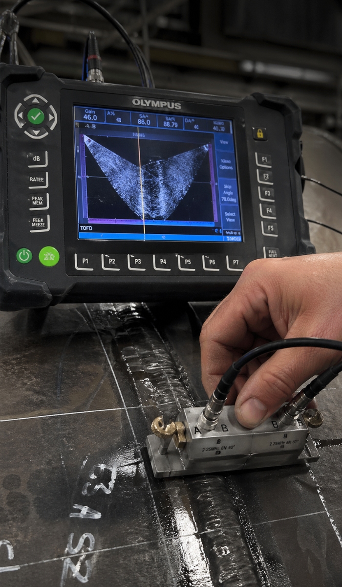
The TOFD technique was first applied in 1985 at the Harwell Center (UK) in response to insistent requests to size cracks in nuclear reactor welds. The TOFD technique is a fully computerized system able to scan, store, and evaluate indications in terms of height, length, scan, store, and evaluate indications in terms of height, length, and position with a grade of coverage, accuracy and speed not achieved by other ultrasonic techniques.
The TOFD technique is based on diffraction of ultrasonic energy from tips of discontinuities, instead of geometrical reflection on the interface of the discontinuities.
This phenomena makes TOFD effective for identifying cracks and lack of fusion located along the vertical axis of the weld (in particular for narrow gap preparation) or with any other orientations, because defect detection is not affected by unfavourable orientation to the primary sound energy angle
Where It Is Used
This inspection method is ideal for identifying defects in:


Weld Inspection in Pipelines
Ensuring defect-free welds to maintain safe and leak-proof pipeline operations.

Power Plants and Refineries
Inspecting critical components to ensure uninterrupted performance and operational safety.

Nuclear Industry
High-precision testing to meet strict safety standards and prevent critical failures.

Heavy Fabrication Structures
Verifying structural integrity in large-scale fabricated components under high stress conditions.
Inspection Process
The inspection process follows a systematic step-by-step approach to ensure
accurate detection of even the smallest surface defects.
Surface Preparation
Cleaning the surface to remove dirt, oil, or contaminants
Probe Setup & Calibration
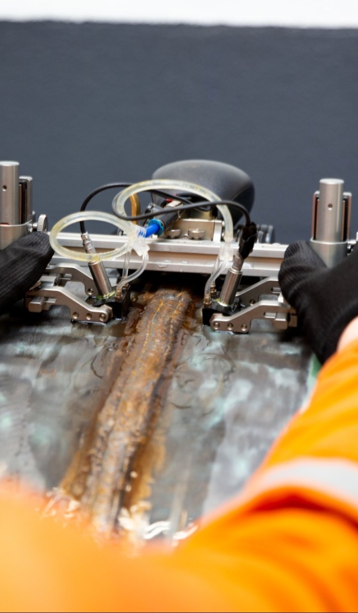
Positioning TOFD probes on either side of the weld and calibrating equipment as per standards.
Couplant Application
Applying couplant to enable efficient transmission of ultrasonic waves into the material.
Scanning Process
Transmitting and receiving ultrasonic waves across the component to capture diffracted signals from defect tips.
Data Acquisition
Recording real-time signals and generating detailed images of internal structures and discontinuities.
Analysis & Reporting
Evaluating defect size, position, and depth with high accuracy and preparing comprehensive inspection reports.
Where It Is Applied (Application)
- Crack sizing and evaluation
- Weld defect inspection
- Replacement of radiography in some cases
- Inspection of planar defects
Key Benefits
- Highly accurate defect sizing
- Faster than conventional UT methods
- Less dependent on defect orientation
- Digital data recording and analysis
Principle of TOFD
Four different types of waves are involved in the construction of a TOFD image: longitudinal wave generated by the transmitter and partially transformed in spherical wave when the beam crosses the tip of a defect the lateral wave that propagates near the surface between the two transducers .The longitudinal wave reflected by the backwall . The shear waves generated by the mode conversion L/T on the interface of discontinuities